
Wastewater Clarifier
CornerStone solution for all settling problems
The major portion of the pollution load carried in wastewater is removed by the biological treatment section of the plant. This section consists of the activated sludge tanks and the final clarifiers, forming together a functional unit. The treatment process is governed by the biomass generated in the aeration tank. This biomass must be separated in the final clarifiers from the wastewater stream and returned to the aeration tank.
From this functional interdependence, the following tasks can be determined for final clarifiers:
- suspended solids in the effluent must be the lowest possible
- the separated biosolids should be withdrawn at the highest possible concentration
- biomass should be held and stored in tank when hydraulic swells occur
- floating solids should not escape in effluent
The final clarifiers determining the overall efficiency of a biological wastewater treatment system, Corner Stone always has intensively and systematically investigated in problems related to this treatment step.
At this time, Corner Stone has a comprehensive knowledge on equipment design and sizing criteria for different types of clarifier tanks and sludge removal systems:
-
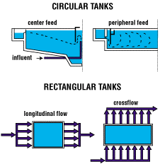
Circular center feed clarifiers with peripheral effluent trough. Rotating blade scrapers for sludge removal.
Tank diameter up to 60 m. -
Circular clarifiers with peripheral feed and takeoff. Rotating suction header for sludge removal.
Tank diameter up to 60 m. -
Longitudinal flow rectangular clarifiers. Submersed pipe system or open air troughs for effluent. Scraper sludge collectors with non-metallic chains, Corner Stone design.
Maximum tank size: length 100 m, width 9 m. -
Cross flow rectangular clarifiers. Sludge withdrawal by suction header suspended to traveling bridge.
Maximum tank size: length 70 m, width 20 m
Activated Sludge Process
The activated sludge process is widely adopted as a processing method for wastewater containing a high concentration of organic matters, such as wastewater from food industry or city sewage.
But, since the activated sludge process utilizes microorganism with a slow growth rate, it has such problems that it runs only in a low BOD volume load, about 0.5 kg/day, it sometimes occurs bulking to causes a failure in sedimentation, and generates excess sludge requires extra cost to be processed.
In the industrial wastewater treatment, because of an increase in BOD load due to plant expansion, or a change in load due to seasonal variation of products, there are cases where it runs near the limit of specified conditions.
Furthermore, the activated sludge process makes use of biological metabolism, and it is necessary to run and control it to optimize the conditions for the microorganism.
On the other hand, BIOATTACK is a highly efficient and easily operated and controlled process where a high concentration of BOD load is treated with a compact unit at a low running cost with high efficiency.
Principles and Outline of Equipment
BIOATTACK comprises of two processes, ATTACK vessel and RECEIVE vessel to run a two-step activated sludge process.
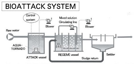
In the ATTACK vessel, by a rapidly growing microorganism group, using AQUA-TORNADO, which is a highly efficient aeration and mixing unit, about 70-80% BOD contents in the wastewater can be disintegrated in a short period.
Next, in the RECEIVE vessel, the Protozoa group with good sedimentation property catches and disintegrates the microorganism group and the remaining BOD.
Features
Stable processing of high concentration BOD
The microorganism having a high growth rate carries out efficient processing, and stable treatment is possible because it adjusts itself flexibly with the variation of water quality.
Compact processing unit and low cost
The BOD digesting rate is approximately 30 times that of the standard activated sludge process, thus the volume of the processing unit may be reduced to about one third of the activated sludge process unit.
Large reduction in the activated sludge generated
The rapidly growing microorganism group has also a high autolysis rate, and further the sludge generated is reduced to about one half of that in the activated sludge process due to the Protozoa preying to create a food chain.
Suppression of bulking
Since almost all the organic matters in the wastewater are disintegrated in the ATTACK vessel by the high-growth rate microorganism group, filamentous fungi may not grow, which are the cause for bulking.
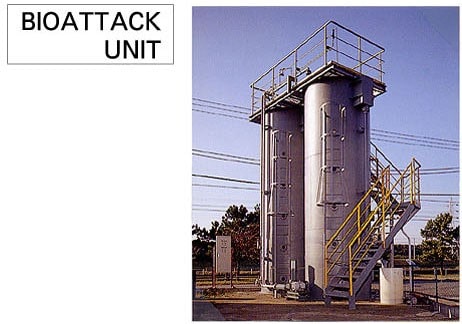
Easy expansion of the existing activated sludge process unit
By adding a compact and easy-to-install "BIOATTACK UNIT", the capacity of the existing unit may be greatly increased. "BIOATTACK UNIT" for extension comprises the following.
Fields of Application
- Wastewater of high BOD load
- Not much space is available for installation.
- Reduction of the excess sludge.
- Reduction in the load of operation and control necessary due to bulking
Package Sewage Treatment Plant Features
Waste treatment plants are available in sizes from 30 cubic meters to 1000 cubic meters per day. All these sizes are manufactured at the company's factory in Al-Zafaraniya and shipped ready-to-run to the job site. Special stations are available for hospitals and industrial projects.
LOW COSTS.
Consist of:
- Small footprint/land area required
- Low energy requirements
- Minimal labour input
- Minimal capital costs
Operation:
- High quality final effluent:
- BOD & SS < 5 mg/l
- Nitrification < 5 mg/l
- P removal to < 5 mg/l
- Ease of operation
- Reduced maintenance
SANITARY SAFETY
- Minimal noise level
- Minimal concentration of pollutants in the air
- Minimal odors gas emissions
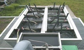
BIOBED® SYSTEM
1. Outline of Equipment
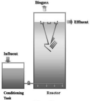
This is a waste water treatment system for low to high organic waste water called EGSB ( Expanded Granular Sludge Bed ) , high-loading type of the UASB (Upflow Anaerobic Sludge Blanket). (Fig. 1)
The organic waste water is firstly led to the conditioning tank where the BOD compounds are degraded to volatile fatty acids (VFA). Both the temperature and the pH are also adjusted there. Then the waste water is introduced the lower part of the reactor via well-designed distributor nozzles, going up with some high velocity and discharged from the three phase ( Gas-Solid-Liquid ) separator: settler at the upper part of the reactor.
A lot of the anaerobic granular sludge is present in the reactor and degrades the VFA to CH4 and CO2. The section of the Biobed® reactor is designed smaller compared to the one of the UASB reactor, resulting in the high upward velocity of both the gas and liquid. That helps the granules move easily and improves the performance.
The energy recovery can be possible from the gas produced by the way of a boiler or a fuel cell etc. The system is fully closed so that an odor treatment is not needed and it has an advantage to a corrosion problem.
2. Characteristics
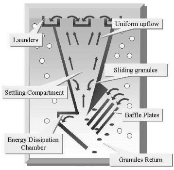
In the EGSB system as well as the UASB system, the main feature is applying of the anaerobic granules and the settler that prevents them to wash out from the reactor. The settler is the most remarkable feature of the Biobed®. It was developed through the hydraulic studies of view to sustain the high upward velocities of both the water and the gas. (Fig. 2)
- Multiple baffle system
The multiple baffles are installed at the lower part of the settler to guide the gas away from the settling compartment. The circulating stream occurs around the gas baffles by the effect of gas-lift theory. In the Biobed® system, the reactor is designed to be high upward velocities.
However just single baffle can not control bringing the gas into the settling compartment against the high stream. It's proved that multiple baffles can solve this phenomenon.
- Energy dissipation chamber
The water coming from the baffles has to leave the reactor via the settling compartment. The way the water is introduced in this compartment is crucial and prevents the granules to settle. The energy dissipation chamber takes out the energy and makes an easy settlement of the granules.
- Settling Compartment
The steep angle promotes an easy settlement of the granules. The shape of this compartment makes the upward stream uniform and there are no local areas where the upflow velocity is higher than the settling velocity of a granule. The granules can slide back through a thin boundary that can exist due to the laminar conditions in the settler.
3. Performance
The volumetric loading of the Biobed® is generally 20 to 30kgCODcr/m3 d for the waste from a food industry. The CODcr removal efficiency is 70 to 90% and the effluent can be discharged to the sewage. In the case of the discharge to a river, an aerobic treatment will be needed.
In the actual treatment of toxic formaldehyde, 8000mg/l in the influent could be removed to less than 20mg/l in the effluent. The plant has been operated well.
4. Adaptable Fields
The Biobed® can be applied to following fields.
- Food: Sugar, Vegetable & Fruit processing, Dairy, Candy, Beverage, Potato etc.
- Fermentation: Yeast, Citrate, Ethanol etc.
- Chemical: DMT, PBT, PET, PO etc.
- Pulp & Paper: Pulp, Recycle paper etc